

Characteristics:
1. Adopting a 32-bit motor control dedicated chip
2. Voltage level 12VDC~48VDC, supporting wide voltage input
3. Support multiple speed regulation modes (PWM, analog, communication)
4. Equipped with control functions such as start stop, forward and reverse rotation, braking, etc
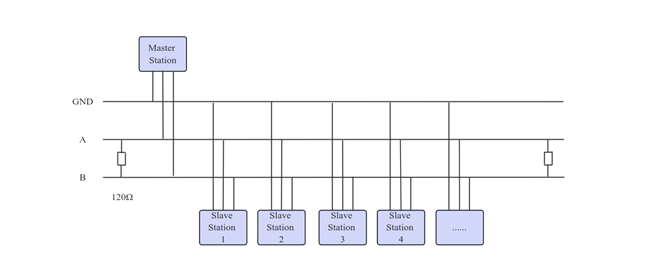
5. RS485 communication, supporting Modbus communication protocol
6. High precision speed and current dual closed-loop control
7. Ultra high cost-effectiveness, cost-effective and efficient
8. cceptable customization
Typical applications:
Widely used in various small and medium-sized automation equipment and instruments, such as electronic processing equipment, 3C non-standard automation equipment, screw locking machines, wire stripping machines, winding machines, terminal machines, laser machines, marking machines, spray painting machines, small and medium-sized carving machines, automatic grabbing equipment, specialized CNC machine tools, packaging equipment and robots.
Product Overview:
The iBLD57NR-H-T series integrated closed-loop brushless motor is a high-performance closed-loop motor independently developed by CHANGZHOU FULLING MOTOR CO., LTD. It adopts a 32-bit dedicated motor control chip, with high integration, small size, and complete protection measures. This motor adopts a new PWM control technology, which makes the brushless motor operate with advantages such as high rotation, low vibration, low noise, and good smoothness.
Speed regulation mode control:
IBLD57NR-H-T provides three speed regulation modes that users can choose from (configured through the upper computer):
External analog speed regulation: By using Fulling's upper computer software, set the control mode (0x0002) to 0, and speed regulation can be achieved through external analog output or potentiometer (recommended potentiometer 5K~100K).
External PWM speed regulation: By using Fulling's upper computer software, the control mode (0x0002) is set to 1 or 2. A pulse width digital signal (PWM) with an amplitude of 5V and a frequency of 1KHz-20KHz can be applied between SV/PWM and GND for speed regulation. The motor speed is linearly adjusted by its duty cycle.
Communication speed regulation: By using Fulling's upper computer software, set the control mode (0x0002) to 3, set the target speed (0x0004), and set the communication start stop (0x0003) to 1.
Communication wiring diagram:
Control Port(B08B-PASK-1(LF)(SN) 8-bit pin)
Pin number | signal | function | Explanation |
1 | TR2 | Terminal resistor terminal | TR2\ TR1 Short circuiting will connect to the terminal resistor |
2 | TR1 | Terminal resistor terminal | TR2\ TR1 Short circuiting will connect to the terminal resistor |
3 | SV/PWM | Speed regulation signal (Can be configured by communication) | Analog speed control: 0.5V~4.5V, PWM speed regulation: Duty cycle polarity configurable 0~5% Full speed 5~95% Linear speed regulation 95~100% cease |
4 | PG | Speed signal | TTL-5V level,1 pulse /1 Antipolar / rotate |
5 | BK | Brake signal | Invalid when suspended or connected to a high level (1.7V~24V) Connected to low-level brake effective (0V~0.8V) |
6 | F/R | Directional signal | CW\CCW High and low level polarity can be configured by software High level(1.7V~24V) Low level (0V~0.8V) |
7 | GND | Sensor power supply Ground | Sensor power supply ground, shared with main power supply ground |
8 | +5V | Sensor +5V power supply | Sensor +5V power supply, Output current <=30mA |
Power Port (B06B-XASK-1(LF)(SN) 6-bit pin)
Pin number | Signal | Function Description |
1 | VDD | Power input positive terminal,input voltage 10V~50Vdc |
2 | GND | Power input negative terminal |
3 | A | Communication RS485-A |
4 | B | Communication RS485-B |
5 | A | Communication RS485-A |
6 | B | Communication RS485-B |

Copyright 2023 Copyright Changzhou Fulling Motor Co., Ltd
【 Disclaimers 】